« Posts by Terry

Crow Sculpt Final

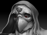
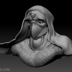
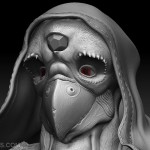
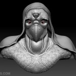
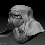
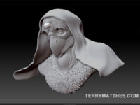
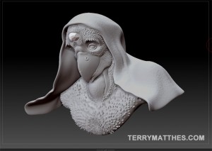
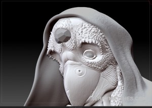
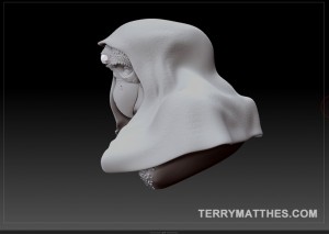
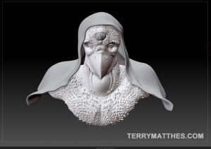
Hey everyone, just posting some final shots of my crow sculpt after several long evenings. The major change you’ll notice from the previous update is the feather treatment. On the old sculpt I used the snake hook tool to pull geometry out for the feathers. In the end I wasn’t happy with how this technique looked. For the final I created a few custom feather alphas. I would stamp a row of the feathers and then mask them off and pull out the next row, continuing this process until the entire chest was covered. For an initial foray into Zbrush I am happy with the results here, but I think that I need to learn more about the layers options and morph targets. The undo system seems somewhat tricky to work with and there were several occasions when it didn’t work at all. I also learned that my system can’t handle merging 3 different 13 million poly meshes. I’d chuck more RAM in, but I’m already at my boards 8GB max. I hope you all have a nice remembrance day.

Final crow - perspective (http://www NULL.terrymatthes NULL.com/wp-content/uploads/2011/11/CrowFinal_persp2 NULL.jpg)Final crow- close up (http://www NULL.terrymatthes NULL.com/wp-content/uploads/2011/11/CrowFinal_close NULL.jpg)Final crow - centered (http://www NULL.terrymatthes NULL.com/wp-content/uploads/2011/11/CrowFinal_center NULL.jpg)Final crow - side view (http://www NULL.terrymatthes NULL.com/wp-content/uploads/2011/11/CrowFinal_persp NULL.jpg)

Zbrush – Crow Man

Perspective view of sculpt

Say hello to “Crow Man”, my first Zbrush sculpt. On Monday we started learning Zbrush in class and it’s been a lot of fun. When I start learning a new program I usually have this insane drive to do everything the “proper” way. Zbrush has so many tools and features it’s actually a little scary. Instead of learning every little detail of the work flow I’ve decided just do use the basic features and work my way through this sculpt. I’m finding this is letting me get more work done and is interrupting my creative flow a lot less. Sure I might not be doing everything the most efficient way, but I think it’s a better way to get your feet wet.

I’d like to say that this piece has a lot of inspiration from one place or another, but to keep with my “loose” method I’ve just been sculpting in whatever pops into my brain. That’s not to say that I’m without reference though. After deciding to do a crow I compiled several images of crows and black birds. I’ve also got a few of my human anatomy references up for the skull and torso. I’ve really tried to push the geometry of the skull to extremes so that the character really has a distinct face. Birds are also related to reptiles so I’ve tried to work in a few lizard like features of offer some artistic variety. You can see this in the bony mounds around the eyes.

The reference has proved most useful to me for the fine details. It’s easy to imagine the large forms and features in your head, but as you increase the detail it becomes a lot harder to just imagine a lot of those finer elements. I’ve got a lot of snes and early console RPG references floating around in my head and those games never had this finer detail because it wasn’t technically possible. The hardest part of this sculpt for me is knowing what each brush does. There are so many and each can be manipulated to a near infinite degree.

For the majority of the sculpt I have been using 4 brushes: standard, pinch, inflate and move. At lower detail levels the move brush has been great for pulling gross forms around and altering the profile of the character. The standard brush has been used for building up the surface in places, and the pinch and inflate are awesome for popping detail out of the surface. All in all this has been pretty fun and I still have yet to paint and texture it. We will be learning how to do that this week in class. I’ll post the painted version when it’s done. If things go well I’ll take it into Maya and use mental ray to pop out a nice render :)

Perspective view of sculpt (http://www NULL.terrymatthes NULL.com/wp-content/uploads/2011/11/perspective NULL.jpg)Detail view of sculpt (http://www NULL.terrymatthes NULL.com/wp-content/uploads/2011/11/detail NULL.jpg)Side view of sculpt (http://www NULL.terrymatthes NULL.com/wp-content/uploads/2011/11/side NULL.jpg)Center view of sculpt (http://www NULL.terrymatthes NULL.com/wp-content/uploads/2011/11/center NULL.jpg)

Breakfast Still Life – Final

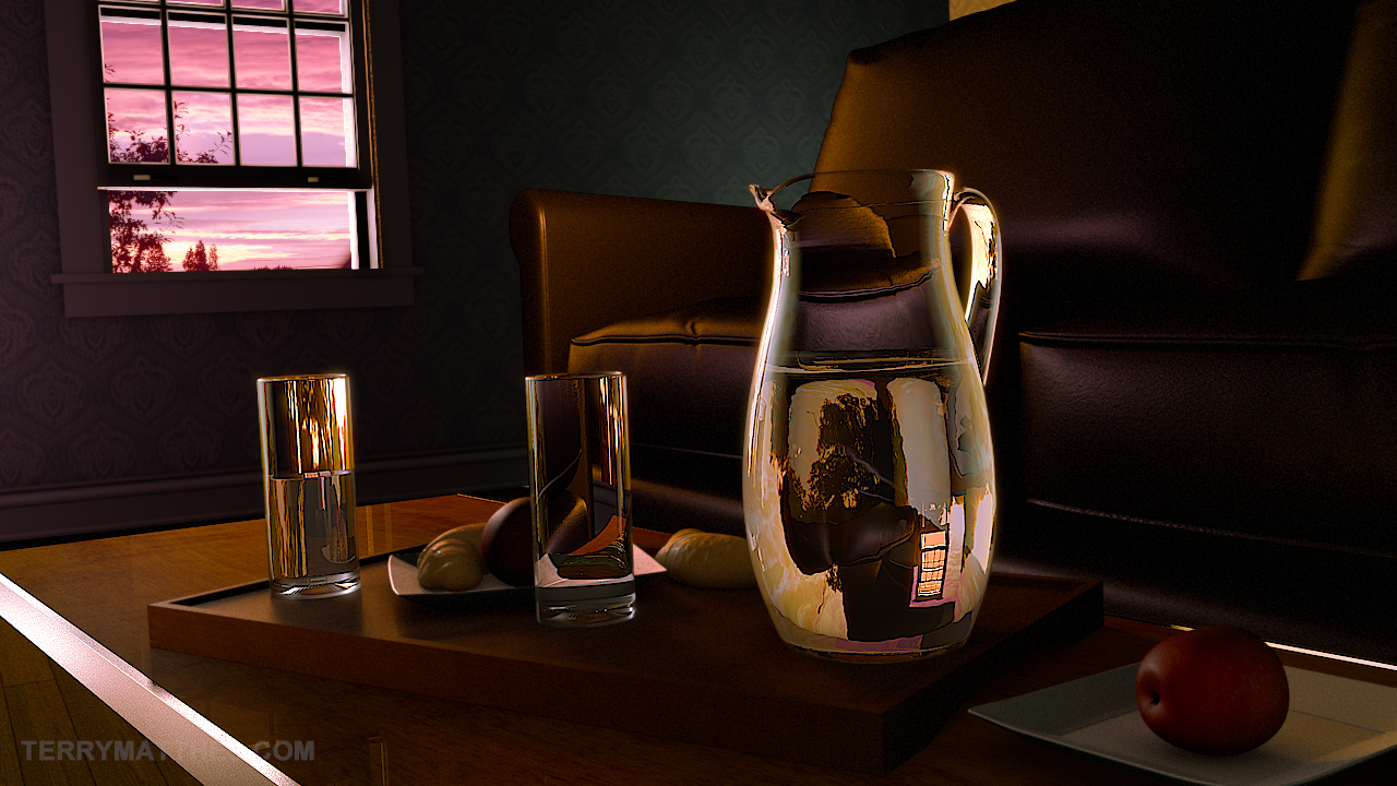
Final Post Edited Render

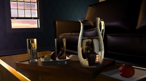
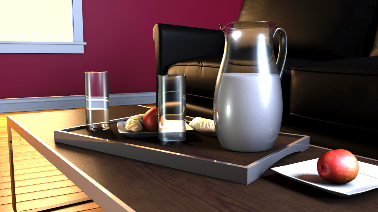
I finished the still life from my last post and then went ahead and did some post work in Fusion. All the major elements in the scene were rendered out on separate render layers in Maya. At first render layers seemed like a lot of work, but after setting them up the benefits are awesome. As always if you have any questions about the work flow feel free to leave a comment or email me. For those hoping to see pastries in the foreground… I’m sorry. I didn’t have enough time to give those croissants the care they needed. GG pastries in Mental Ray. GG.Below are my rough draft and raw render along with the final image. Next time I do a light setup I’m going to try and use the light fog in Maya instead of relying on Fusion. This is the first time I’ve ever used film grain in post and I think it may be a little heavy handed, but in my defense shooting in that low light would give you some strong grain.

Glass Render from Mental Ray (http://www NULL.terrymatthes NULL.com/wp-content/uploads/2011/10/PrePostStillGlass NULL.jpg)

Glass render untouched from Mental Ray

Early Test Render (http://www NULL.terrymatthes NULL.com/wp-content/uploads/2011/10/glassesRough NULL.jpg)

Rough Render for 3D Still

Final Post Edited Render (http://www NULL.terrymatthes NULL.com/wp-content/uploads/2011/10/TerryMatthe_GlassFinal NULL.jpg)

Breakfast Still Life – Rough

Rough Render for 3D Still Life involving glass

This image was created for my rendering class in college. We were given the objects and asked to properly light and render them. The style of render was left up to us. The challenge with this assignment is to get the glass looking right. Most of the objects needed to be unwrapped so that’s the first thing I did. Unlike my last apartment render (http://www NULL.terrymatthes NULL.com/general/news/apartment-final-render-thoughts/) this piece can contain no global illumination or final gather. Any bounced light is simulated with secondary light sources. I had to remodel the glasses as their were lots of strange triangles buggering up the reflections. The pitcher and the glasses have separate faces for the inside and outside of the object. Under the glass mesh render properties the objects are set to one sided.

One thing to keep in mind while rendering glass in Maya and Mental Ray is black surfaces. If you are rendering a translucent or semi translucent object and you are getting black artifacts or faces on your render then you need to increase your reflection rays in the object’s material properties. Reflections and refractions take a long time to render due to the amount of ray casting going on. Too many rays and you can drastically increase your render time. Too few and you’ll get black faces where the rays didn’t penetrate the objec. Reflections are a little tougher as you actually have to know what should be reflected. If you can’t see them at all it’s a littler tougher to guess which ones are missing. If you’re casting enough rays within each material and you’re still getting black faces then chances are you have not set your ray tracing limits high enough in the scene’s render settings. In case you didn’t know there is a master ray trace control found under the “Quality” tab in the render settings window.

The colours of the piece are still pretty loose. I was playing around with Adobe Kuler (http://kuler NULL.adobe NULL.com/) and though it was a pretty fun tool to choose a colour pallet. My biggest problem at this point is the strength of the lighting in relation to the floor reflections. I’d like to keep the light warmer (3500k), but I’d also like to get some less harsh reflections in the floor. Most of what’s left to do involved tweaking materials and finalizing a colour pallet. I might take a swing at Maya fur again, but we’ll see if time allows it. I’ve been working part time in while going to school and it’s really been cutting into the amount of time I have to get homework (let alone personal projects) done. I would cut my hours down, but at my work the minimum for part time is 20. I did find a wonderful way to save time though… I set my computer up so I can login remotely. This makes it a lot easier to setup and look at renders. I suppose I could just batch render multiple files with a script, but I wouldn’t be able to change anything after I leave home. I don’t know about you guys, but I frequently get hit by ideas while out and about and this lets me incorporate those changes into the renders.

Rough Render for 3D Still Life involving glass (http://www NULL.terrymatthes NULL.com/wp-content/uploads/2011/10/glassesRough NULL.jpg)

Fruit Bowl Render

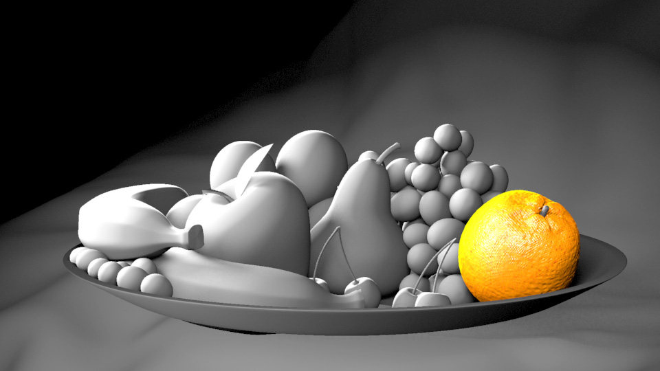
black and white fruit bowl

In our lighting and rendering class we are going through the basics of mental ray lighting with linear work flow. I’ve done a bit of this on my own as you might know if you keep up with this blog. I’m learning a lot about the different tools you have in Mental Ray to control shadows and blurry reflections. Our first assignment is to light and render a fruit bowl that as supplied to us. I’ve just started this assignment and I only have the orange texture started, but I have finished lighting the scene. We aren’t allowed to use any indirect lighting systems like Final Gather or Global Illumination. Any bounced light has to be simulated. I’m going to add coloured point lights to simulate bounced light after I have my textures setup.

Most of these lights are casting ray traced shadows with a light radius of 5, 40 shadow rays, and 2 bounces per ray. There is a bit of light linking going on so I can illuminate the bowl and drop cloth separately. For this coming Monday we have to have at least one of the fruits textures started. I have chosen to start with the orange. I generally like the texture, but I have to make a new bump map that puts all those little circular bumps across the surface. The current bump isn’t dense or varied enough.

(http://www NULL.terrymatthes NULL.com/wp-content/uploads/2011/09/lightrough1 NULL.jpg)
As always, if you have any questions about the settings or any of the file setup just post em here or email me.

Material Editor Keyboard Shortcuts

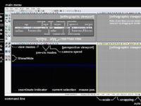
Unreal Development Kit User Interface Diagram

Posted these shortcuts a while ago at Eat3D (http://www NULL.eat3d NULL.com). I though I would repost them here to share with anyone who doesn’t frequent that site. If you aren’t though you should. They have amazing video tutorials.

Material Editor Shortcut Keys

Num Key 1 1 variable constant

Num Key 2 2 variable constant

Num Key 3 3 variable constant

Num Key 4 4 variable constant

E key Power node

R key Reflection Vector

T key Texture Sample

U key TexCoord

I key If node

O key 1-x node

P key Panner node

A key Add node

S key Param ‘None’ (0) node

D key Divide node

L key Lerp node

C key Mask (R G) node

V key Param ‘None” (0,1,2,3)

B key BumpOffset node

N key Normalize node

M key Multiply node

Unreal Unit Meshes – “UBlocks”

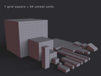
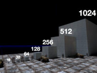
Unreal Block Meshes

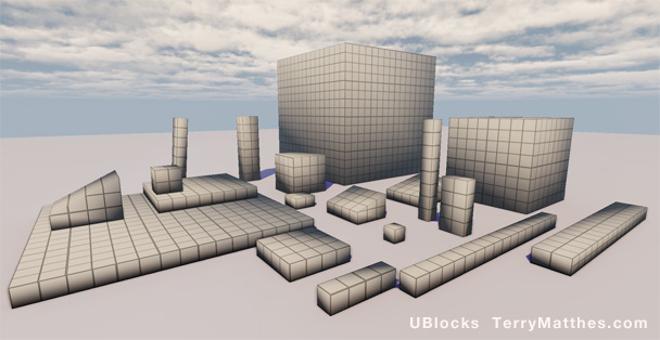
After digging into the 2DPlatformerStarterKit (http://udn NULL.epicgames NULL.com/Three/DevelopmentKitGemsPlatformerStarterKit NULL.html) I began thinking about how I should go about creating my 2D test level. This level would be a staging ground for all sorts of pre-production tests. Things like lightning, particle systems, and mesh design would all be roughed out here. I always find if hard to visualize what sizes my meshes should be while working in Maya.  I was thinking that a quick way to rough out the size of a level and it’s meshes would be to use pre sized blocks like LEGO (http://www NULL.terrymatthes NULL.com/wp-content/uploads/2011/08/legos NULL.jpg).

I’ve made several different sizes of cube type meshes that area all using the same parent material. Each square on the grid texture represents 64 units in the Unreal engine. If your Maya grid isn’t setup  to work with the UDK change your grid settings to match these values…

Maya to UDK Grid Settings – Length and Width:2000 Grid Lines Every:64 Subdivisions:8

(http://www NULL.terrymatthes NULL.com/wp-content/uploads/2011/08/ublocksweb NULL.jpg)

UBlocks in default UDK Scene

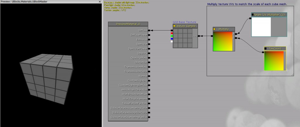
The material network is pretty self explanatory, but I’ll go over it quick. There is a texture coordinate node that is being multiplied my a custom parameter node. This lets you control the parameter node’s value separately in all instances of this material. The “U” and “V” coordinates in the “Texture Coordinate” node are represented in the texture by red and green. Multiplying this node’s output will multiply each color channel in the texture. Increasing the value of red and green will tile the material. The new multiplied red and green values are then plugged into the grid texture’s UV input.

Shader network for UBlock parent material (http://www NULL.terrymatthes NULL.com/wp-content/uploads/2011/08/ublocks_mat NULL.jpg)

Shader network for UBlock parent material

Download UBlocks (http://www NULL.terrymatthes NULL.com/public/UBlocks NULL.zip) – I don’t mind if you redistribute the meshes with your projects, but please link this post or include the original ZIP file in your download.

UDK Platform Starter Kit Scene Scale

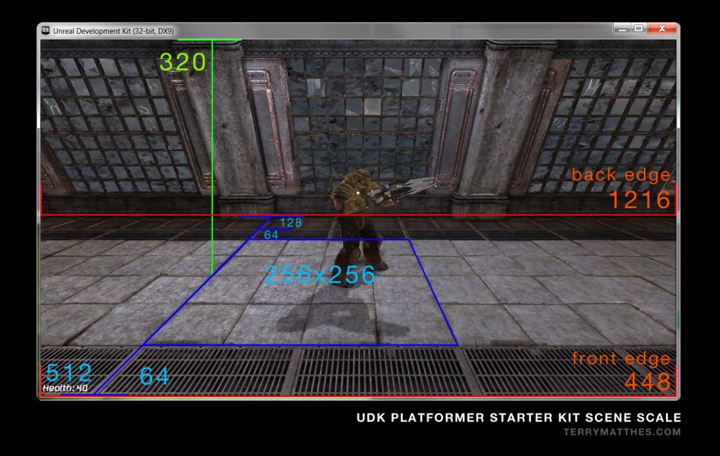
Unreal Development Kit Scale Chart

I was checking out the Unreal Developer Network (http://udn NULL.epicgames NULL.com) last night and found out they’ve released what is essentially a template for a 2D platformer (http://udn NULL.epicgames NULL.com/Three/DevelopmentKitGemsPlatformerStarterKit NULL.html). My brain just about exploded when I saw this. I’ve been trying to code my own bare bones 2D platform game class for quite some time, but most of my skills are geared towards art. I did however purchase the Introduction to Unreal Script (http://www NULL.eat3d NULL.com/unrealscript) from Eat3D.com (http://www NULL.eat3d NULL.com/). It helped me setup a proper development environment for the UDK, but I found the technical depth quite shallow. I guess that shouldn’t surprise me given that it’s an introduction :\

At any rate the documentation for the kit is pretty decent and if you have a basic understanding of level design you should be able to jump right in and start building your own levels and swapping characters. Before I went to work today I took some measurements of an in game shot to get an idea of the mesh sizes I’ll need to create in Maya. If you’ve never created anything for the Unreal Development Kit in Autodesk Maya then the first thing you will want to do is adjust your scene scale. Here is a YouTube video (http://www NULL.youtube NULL.com/user/jonathanvillaverde#p/u/18/v62ZJhryFP4) from Jonathan Villaverde’s channel (http://www NULL.youtube NULL.com/user/jonathanvillaverde) to help you get that done.

Default 2D Scale Measurements for UDK 2D Platformer Kit (http://www NULL.terrymatthes NULL.com/wp-content/uploads/2011/08/ScalePlatform2D NULL.jpg)

Default 2D Scale Measurements for UDK 2D Platformer Kit

UDK Intro: Geometry Mode

Default 2D Scale Measurements for UDK 2D Platformer Kit

Introduction

You will have to recalculate the BSP every time you want to see the changes you have made.

This lesson will cover the use of geometry mode to transform a brush’s shape, or create an entirely new brush. There are several different ways a brush can be manipulated in “geometry mode” .  Select your builder brush and then hit the geometry mode button (diagram 1).
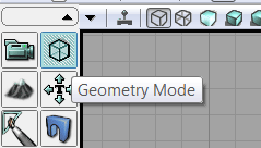
Unreal Development Kit "Geometry Mode" Button (http://www NULL.terrymatthes NULL.com/wp-content/uploads/2011/07/BSP01_02 NULL.png)

Diagram 1: Geometry Mode Button

Basic Polygon Components (http://www NULL.terrymatthes NULL.com/wp-content/uploads/2011/07/BSP01_01 NULL.png)

Diagram 2: Polygon Components

If you are in geometry mode all corners of your builder brush will have turned into large red squares. When manipulating your brush you should keep the different components of a brush in mind (diagram 2). Using these components often and effectively will save you time. Lets change the position of our “Builder Brush” components using the transform tools. Start by making sure the geometry mode has been turned on.

Tools
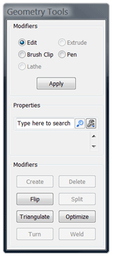
Unreal Development Kit Geometry Tool Options (http://www NULL.terrymatthes NULL.com/wp-content/uploads/2011/07/BSP01_03 NULL.png)

Diagram 3: Geometry Tool Options

Edit
While in edit mode you can select and manipulate single or grouped vertices, edges and faces. Try selecting one of the vertices and then hold down CTRL and select a few more. There are no options in the “Properties” section (diagram 3) of the Geometry Tool for edit mode.

Extrude
This mode is available exclusively for manipulating the faces of your geometry. To access this mode you will first have to select a face that belongs to your brush. Only after doing this will the radio button become available.


(http://www NULL.terrymatthes NULL.com/wp-content/uploads/2011/07/bsp01_04 NULL.gif)
To extrude a face simply select the face you want to extrude and pull outwards on the coordinate handles. For a more precise extrusion you can enter the “Length” and “Segments” of your desired extrusion into the “Properties” section. A properly extruded face can be seen in diagram 4.


Don’t forget you can also affect the translate handles without pulling on them. Try using these commands:


  • translate X = LMB + CTRL
  • translate Y = RMB + CTRL
  • translate Z = LMB + RMB + CTRL
Unreal Development Kit Geometry Extrude (http://www NULL.terrymatthes NULL.com/wp-content/uploads/2011/07/BSP01_04 NULL.png)

Diagram 4: BSP Extrude Example

Brush Clip
Have you ever wanted to split a brush in two, or perhaps make two brushes from a single brush. If so the “Brush Clip” tool is just what you need. In the orthographic view port hold down the CTRL key and click with the RMB. You need two points that clearly cut across your brush to make the clip work (diagram5). Click “Apply” and you will notice that your brush has been split. You should also notice a line perpendicular to your clip line. This line is the “normal”.

Unreal Development Kit Brush Clip (http://www NULL.terrymatthes NULL.com/wp-content/uploads/2011/07/BSP01_05 NULL.png)

Diagram 5: BSP Clipping Example

The normal direction is changeable in the “Properties” section. Reversing the normal will reverse the cut. The normal has to be flipped before the cut is made to have any affect on the brush. Underneath “Flip Normal?” is the option “Split?”. This option will take the part of the brush that is usually clipped off and create a separate brush out of it .

Pen
The pen tool can create new brushes from points you lay down in a orthographic view. To create a brush connect three or more points ending at the first while holding down CTRL and clicking the RMB. The shape is set to auto extrude to a depth of 256.

Try connecting a punch of points together in a random shape. You will notice that the shape extrudes in the coordinate that matches its view. For an example of this create a shape in the top orthographic view and notice that it has been extruded along the Z axis. This extrusion will follow the world coordinate associated with the orthographic view you created it in.

In the “Settings” section you will notice several different options available to you. If “Auto extrude?” is turned off you will not get a default coordinate extrusion when you complete your pen path. The “Create Brush Shape?” option is used in conjunction with several features including the “Lathe” tool. When creating a shape you will notice that the editor always triangulates your shape. If this is something that you don’t want you can tick off the “Create Convex Polygons?” option and your new shapes will consist of quads and n-gons (diagram 6). Our last option is “Extrude Depth”. This is the default extrusion depth your pen tool will create when completed.

Regular vs. Convex Geometry (http://www NULL.terrymatthes NULL.com/wp-content/uploads/2011/07/BSP01_07 NULL.png)

Diagram 6: BSP Clipping Example

Lathe
The “Lathe” tool tries to take your shape and revolve it 360% around the dominant coordinate of your current orthographic window. The “Lathe” option can only be selected if you create a polygon with the “Pen” tool while the option “Create Brush Shape?” is turned on. Your shape will be green in colour.

The last two options will help to control how much of a 360% sweep your shape will occupy. The “Total Segments” option will set how many segments will make up the whole 360% turn. The “Segments” section will determine how many of those segments to actually produce.

Let’s make a simple square with the “Pen” tool and the “Auto Extrude?” option turned off. Start in the top orthographic view and make your four point selection (diagram 7). Now highlight the Y coordinate view (top right by default) and re-select your pen shape. In your options box set your “Total Segments” option to 16 and your “Segments” to 8. Now go ahead and lathe your selected shape.

You will notice that the inner radius of the lathe makes a semi circle. This is because our “Segments” option was set to half of our “Total Segments”.

Unreal Development Kit Lathe Example (http://www NULL.terrymatthes NULL.com/wp-content/uploads/2011/07/BSP01_08 NULL.png)

Diagram 7: BSP Lathe Example


Modifiers

Delete
Faces and verticies may be deleted using the “Delete” tool. Be careful when deleting. Look at your geometry closely and make sure you won’t get any unwanted shape changes from the deletion. Any faces you delete can always be repaired by using the “Create” modifier.

Create
Great for filling holes or bridging BSP the “Create” modifier works using verticies. Add a simple cube brush to the world and  delete one of it’s faces.Now select the four verticies around the open face in a clockwise fashion and then hit ENTER. The face will have been created with its normal direction facing outwards (diagram 8). If you were to make the same selection counter-clockwise the face will have been created pointing inwards.

Unreal Development Kit Create Face Example (http://www NULL.terrymatthes NULL.com/wp-content/uploads/2011/07/BSP01_09 NULL.png)

Diagram 8: BSP Create Face

Flip
That thing we just talked about called the normal; it’s what the “Flip” modifier is all about. Working on faces, the Flip modifier reverses normals. Reversing a face’s normals flips the side of the polygon that is rendered. This is why you can’t see the insides of meshes when you pass through them in spectator mode. The normal for all of those faces is pointing outwards.

Triangulate
Fairly self explanatory, “Triangulate” breaks mesh faces up into triangles (diagram 9). If you notice a surface of your BSP is rendering funny triangulate the faces giving your the trouble. Chances are they’re n-gons of some sort. Try creating a cube brush and selecting it’s top face. Now triangulate that face and notice how that quad (four edged  polygon) was broken up into two tris (three edged polygon).

Unreal Development Kit Geometry Mode Triangulation (http://www NULL.terrymatthes NULL.com/wp-content/uploads/2011/07/BSP01_10 NULL.png)

Diagram 9: BSP Triangulation

Turn
If you have two triangles on a brush that share a common edge you can “Turn” that edge .This rotates the the common edge of the triangles. Doing this causes the line that connects the two triangles to snap the the other 2 verticies that make up their 4 verticie border (diagram 10). If you still are unclear on this try using the pen tool to make a non extruded shape. Now “Triangulate” this shape and practice turning some border edges of triangles around.

Unreal Development Kit Turn Edge (http://www NULL.terrymatthes NULL.com/wp-content/uploads/2011/07/BSP01_11 NULL.png)

Diagram 10: BSP Turn Edge

Split
The “Split” tool adds “edge loops” or a series of verticies that run around your mesh connected by edges. Create a cube and select one of its edges and then use the Split modifier. Notice that a line was run around your shape that is perpendicular to the original edge you selected (diagram 11). This will always be the case when Splitting. In conjunction with the “Extrude” tool, splitting can work well to help you achieve whatever BSP shape you need. Diagram 13  illustrates the idea behind this.

Unreal Development Kit Edge Split (http://www NULL.terrymatthes NULL.com/wp-content/uploads/2011/07/BSP01_12 NULL.png)

Diagram 11: Edge Split BSP With Extrusion

Optimize
Using “Optimize” on a group of faces with adjacent edges will create a new polygon in their place that has no edges running though it. Any verticies that are no longer required to keep the shape of the brush will be deleted. Depending how you merge your faces you can end up with some really “interesting” polygons. Try to make sure all your optimizations create quads or tris.

Weld
Verticies can be merged using the “Weld” tool. The position of the resultant merge will be the location of the first verticie you selected (diagram12). Create a cube and select two of the top verticies and Weld them togeather. Now do the same to the other two and then once more so you’re left with one verticie. Move the single remaining top verticie to the middle of the cube in the top orthographic view. You know have a pyramid. Wasn’t that fun?

Unreal Development Kit Weld Vertex (http://www NULL.terrymatthes NULL.com/wp-content/uploads/2011/07/BSP01_13 NULL.png)

Diagram 12: Vertex Welding Steps


Conclusion

To exit geometry mode click the “camera mode” button (it looks like a TV camera) located beside the “geometry mode” button. It’s also of note that to “Undo” picked points with any of the tools you can hit the “ESC” key.