Introduction
This lesson will cover the very basics of the interface while manipulating the “builder brush” with transform tools. For those of you who don’t have it yet the UDK can be downloaded here from Epic Games.
To enhance your transition into the Unreal Developer Kit please accept this assistance: Interface Diagram (http://www NULL.terrymatthes NULL.com/wp-content/uploads/2011/07/udk_interface NULL.jpg)
Startup
After you get UDK installed and running you will notice several different options in your windows start menu. For this lesson we are going to open the one labeled “Editor” (diagram 1) . A “Tip of The Day” window will greet you upon entry. Whether you choose to leave this notice on is up to you. Right now simply click the “OK” button.
 (http://www NULL.terrymatthes NULL.com/wp-content/uploads/2011/07/intro01_01 NULL.png)
Diagram 1: Unreal Development Kit Icon
 (http://www NULL.terrymatthes NULL.com/wp-content/uploads/2011/07/intro01_02 NULL.png)
Diagram 2: Unreal Development Program Tabs
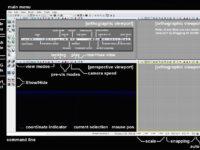
The first window to gain focus after clearing the Tip of The Day button is the “start page”(diagram2). This page is a way for Epic Games to get news and updates to you through the UDK. Close this windows and you should see the main program window behind it (diagram3).
 (http://www NULL.terrymatthes NULL.com/wp-content/uploads/2011/07/intro01_03 NULL.png)
Diagram 3: Unreal Development Kit Main Window
The main program window is where we will be spending the remainder of this lesson. We’ll get to the other window, referred to as the “generic content browser” in the next lesson. Our first objective is to create a new file. There are two types of files we can create. Click on the File menu in the top left corner of the editor and select “New”.
We are given a choice between “additive” and “subtractive”. Generally you are going to want to use the additive level type. Select the additive radio button and click “OK”.
Navigation
Each view port can be maximized so that you can see its contents more clearly by pressing the “maximize view port button”. This button is the last button on the right of your view ports pictograph menu represented by a square with a black top border (see diagram 4). If you are running a dual monitor setup you might be interested in increasing your UDK screen space. To do this click the “tear of a floating copy” button located to the left of the maximize view port button. This button can be seen in diagram 4.
 (http://www NULL.terrymatthes NULL.com/wp-content/uploads/2011/07/intro01_04 NULL.png)
Diagram 4: Tear Off / Maximize World View Panel
Perspective View Port
Translate back and forth by holding down the left mouse button (LMB) and moving your mouse forwards and backwards.
Pan the camera in any direction by holding the LMB and RMB down while moving the mouse.
Free look by holding down the RMB and moving the mouse around.
WASD Cluster
You can hold down the right mouse button and use the classic W,A,S,D key cluster to move around as well. The Q key and R keys can be used to change your camera’s elevation level.
Orthographic View Ports
You’ll have noticed by now that you have three other view ports available to you. These are your orthographic view ports. They are fixed camera views of your level from the top, front, and side. In these views you obviously can’t free look, but you can pan around and zoom.
Take note: if at anytime you feel the camera is moving to slow you can adjust the speed in each view port independently by pressing the “toggle camera speed button” seen here in diagram 5.
 (http://www NULL.terrymatthes NULL.com/wp-content/uploads/2011/07/intro01_05 NULL.png)
Diagram 5: Unreal Development Kit Camera Speed
Basic Geometry Manipulation
On the left hand side of your screen you will notice two vertical rows of basic geometric shapes grouped together. This is your “brush pallet” (see diagram 6). Right click on the cube icon in your brush palette. A window with the primitive’s properties will have popped up and in those properties we can clearly see the X, Y, and Z values for the cube’s dimensions. Click on each field and change the values to the following X:1024 Y:1024 Z:256. Now hit the “build” button and close the window. This red cube wire frame you have created is called a “builder brush” and it represents a shape that you could potentially add to your level. To get a better look at our new red “builder brush” lets navigate closer in the perspective view port.
 (http://www NULL.terrymatthes NULL.com/wp-content/uploads/2011/07/intro01_06 NULL.png)
Diagram 6: Unreal Development Kit Brush/Primitives Palette
This wire frame cube we have added can be manipulated just like geometry in a 3D suite such as Maya or Cinema 4D. You can manipulate geometry in three basic ways: translate, rotate, and scale. All of the tools to do this can be found along with the “undo” and “redo” buttons in the pictograph menu just below the main program menu (see diagram 7).
 (http://www NULL.terrymatthes NULL.com/wp-content/uploads/2011/07/intro01_07 NULL.png)
Diagram 7: Unreal Development Kit Undo / Redo Buttons
The first button that looks like a mouse is your “selection” tool. If at anytime you lose focus of an object your manipulating you can simply select this tool and click on your object. You can’t manipulate geometry in this mode.
Translate
This button is located to the right of “selection”. You can use this tool to move your object around in your level by clicking one, or combination of two axis arrows. The arrows are colour coded to match their coordinate direction. There is also a coordinate indicator in the bottom left of the perspective window (see diagram 8).
 (http://www NULL.terrymatthes NULL.com/wp-content/uploads/2011/07/intro01_08 NULL.png)
Diagram 8: Unreal Development Kit 3D Coordinate Orientation
Rotate
To rotate your object you highlight one of the coordinate axis orbiting your object and drag. Unlike the translation tool you can’t move in more than one axis at a time.
Scale
Scaling your object can be done in two ways. You can scale your object up and down uniformly, or each coordinate direction can be scaled on it’s own.
To scale uniformly select the large gray square with the little square inside it. This is the bigger of the two gray squares seen side by side. Notice that all coordinate axis handles are red. No matter which one you choose to pull on they will all scale your builder brush in the same fashion.
Non uniform scaling lets you increase the scale of one or two coordinates independent of the remaining coordinate(s) by dragging the handles you want to change. To select multiple handles move your mouse closer to the center of the two handles you want to manipulate.
Take note: You can use any of the manipulation tools as a selection tool. This way you don’t have to go back and forth between manipulation tools and the selection tool.
Conclusion
The remaining intro lessons will be spent setting up very basic map. The goal will be to get you familiarized with the major aspects of the UDK. The topics you’ll be introduced to will include: adding geometry, materials, lighting, static meshes, particles, sound/music, and visually scripted events.
 (http://www NULL.terrymatthes NULL.com/wp-content/uploads/2011/07/udk_interface NULL.jpg)
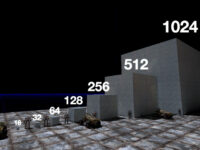
 (http://www
 (http://www
 (http://www
 (http://www
 (http://www
 (http://www
 (http://www
 (http://www
 (http://www
 (http://www
 (http://www
 (http://www
 (http://www