« Posts tagged UDK

UDK Scale Chart

Unreal Development Kit Scale Chart

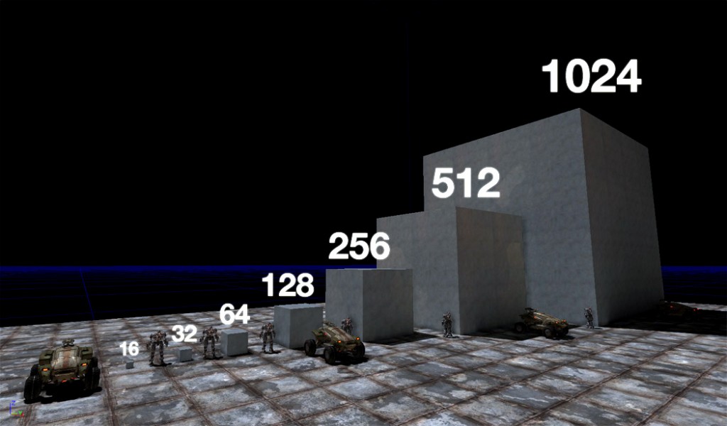
Here’s a scale chart to help you visualize things when you’re moving around in the Unreal Development Kit. Its set against assets from the Unreal Tournament III Game. The white numbers are Unreal grid dimensions. An average character is ~96 units high. To learn how to setup your Maya grid for proper scale see this this succinct  Youtube Video (http://www NULL.youtube NULL.com/watch?v=Xl5kJP02K0g). Peace.

Unreal Development Kit Scale Chart (http://www NULL.terrymatthes NULL.com/wp-content/uploads/2011/07/udk-scale NULL.jpg)

Unreal Development Kit Engine Scale Guide

Sprite Channel Controller

Channel Controller Network

Introduction

Prerequisites

Maya opticalFX Sprite Textures (http://www NULL.terrymatthes NULL.com/particles/maya-sprite-textures/)

In our past lesson we created 3 different sprites and a gradient mask. Then we put them all into one texture using channels. This lesson will use that texture as a base for a material network. This material network will let us create instances of our base material that will have variables we can change. We will be able to change the inside colour, outside colour, saturation, core brightness, and sprite textures themselves. We’ll start by importing our texture into the Unreal Development Kit. If you don’t have a texture ready to go please run through our last lesson (http://www NULL.terrymatthes NULL.com/particles/maya-sprite-textures/) to get one setup.

Unreal Development Kit

Importing Texture

Let’s bring up the Content Browser (ctrl+shift+f) inside of the UDK and click the import button at the bottom right to bring in our texture. Under the import options for our texture we want to select “TC_SimpleLightmapModification” as the “Compression Settings” and label the group “Texture”. I find that  TC_SimpleLightmapModification is the only section that doesn’t degrade the sprite texture channels. Now that we have our texture imported lets go ahead and create a new material. Right click in an empty area of the Content Browser and select “New Material” name it whatever you wish and call it’s group “Material”.

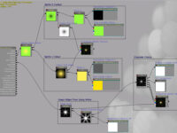
Below is the network we are going to create. We’ll break down each node grouping and explain the elements one by one. You’ll notice that in place of regular constant vectors we have placed scalar parameters and vector parameters. This will let us manipulate these values outside of the Material Editor. All “Parameter” nodes have a “Value” this is what identifies them in the material instance we will create later. You must fill the Value names in and make sure they are unique or you will get nodes sharing values and that isn’t good.
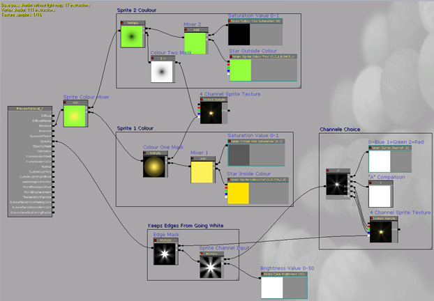
Channel Controller Network (http://www NULL.terrymatthes NULL.com/wp-content/uploads/2011/01/p_101_channelController_network NULL.jpg)

Before we jump into the individual node groupings I just want to drop down a copy of our sprite texture. Select the sprite texture in the Content Browser, hold down the “t” key and click in the Material Editor.
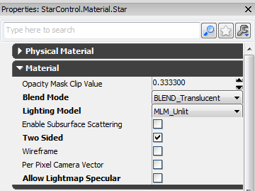
Material Properties (http://www NULL.terrymatthes NULL.com/wp-content/uploads/2011/01/p_101_channelController_matprop NULL.png)The material we are creating is going to be partially transparent and double sided. We need to change some options in the materials properties to reflect this. First click on the material body and then click the “Material” rollout to expand it’s options. Change the “Blend Mode” to “Blend_Translucent” and check the “Two Sided” option.

Make sure you add descriptions to your nodes inside the Material Editor. You can do this inside the node’s properties under “Description”. You’ll want to do this to most nodes along the way so you don’t end up with a mess of nodes later on and have no idea how each functions.

Inside Colour
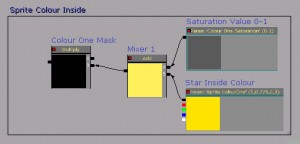
Inside Colour Setup (http://www NULL.terrymatthes NULL.com/wp-content/uploads/2011/01/p_101_channelController_inside NULL.jpg)To build this grouping we are going to drag out the following nodes onto our canvas: Vector Parameter” Scalar Parameter, Add (“a” key) and Multiply (“m” key).

Hookup the output on both the Scalar Parameter and the Vector Parameter to the input of one of the Add nodes. Label this add node “Colour Mixer Inner”. The Vector Parameter will help you choose your inner colour. The Scalar parameter will control how saturated the colour is. 0 will leave the colour at full saturation while 1 will wash it out to white. If you want any white at all in the highlight you’ll want to set this to at least 0.1.

Take the output from the Add node we were using and plug it into one of the inputs on our Multiply node. Now plug the alpha channel (white tab) from our sprite texture into the remaining input. This will mask the inner colour off so it fades towards the edges of the sprite image.

Outside Colour
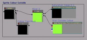
Outside Colour Setup (http://www NULL.terrymatthes NULL.com/wp-content/uploads/2011/01/p_101_channelController_outside NULL.jpg)The outside colour is setup almost the exact same way as the inside colour setup except we are going to reverse the alpha channel gradient of our texture using a “One minus” node. Ctrl+alt drag over the entire inner colour setup and Copy it (ctrl+c), then Paste it (ctrl+v). Now drag out a “One Minus” node from the “Math” section of our Material Expressions menu on the right. Connect the One Minus node in between the Multiply node and the Alpha channel(white tab) of the sprite texture.

The last thing we are going to do with colour is hook these two systems up to the “Emmisive” input on our material. Drop an Add node down and connect the output of both system’s Multiply nodes into either input. This will add the outside and inside colours together by blending the two gradient masks.

Core Brightness

The core brightness will be controlled by a single Scalar Parameter. I suggest using a brightness value of 0-50. Your range might vary though. It really depends on the overall brightness of your channel images.
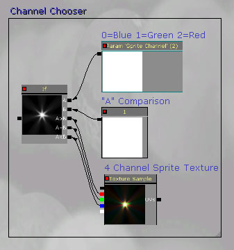
Channel Chooser Setup (http://www NULL.terrymatthes NULL.com/wp-content/uploads/2011/01/p_101_channelController_chooser NULL.jpg)Channel Chooser

Our channel choosing system will revolve around an “If” node. The “If” node allows us setup a greater than, less than, equal to statement that we can use to choose our texture channel. Drag out an “If” node, a Constant1Vector (“1” key), a Scalar Parameter, and an extra copy of our sprite Texture (“t” key).

Set the Vector1Component’s value to 1 and connect it to the “B” input of the “If” node. Connect the Scalar Parameter to the “A” input and set it’s value to “1”.

Connect the red green and blue channels of your sprite texture node to the “If” node as follows:

  • red = A>B
  • green = A=B
  • blue = A<B

Now that our “If” node is setup we can switch between channels. A Scalar Parameter value of 2 will give us the red channel, 1 gives us the green channel, and 0 gives us the blue channel.

Edge Masking

Our last section will consist of two Multiply nodes. Drop 1 down and connect the Scalar Parameter output from our core brightness into input B. Connect the output of the “If” node into input A.

Drop down a second Multiply node and connect the first Multiply node into input B. Now connect the alpha channel (white tab) of our sprite texture into input A. Lastly plug the output of this Multiply node into the Opacity input of our material. Be sure to save your material by pressing the green check mark at the top right now that everything is complete.

Material Instances
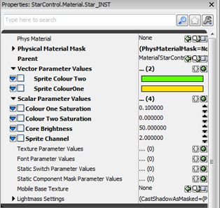
Material Instance Options (http://www NULL.terrymatthes NULL.com/wp-content/uploads/2011/01/p_101_channelController_instance NULL.jpg)Material instances are a good thing. They save us resources by changing materials already stored in memory. The more resources we have the more cool things we can show people :) Let’s create a material instance of our Sprite Material by right clicking on our material in the Content Browser and select “Create Material Instance (Constant). Rename the instance if you wish. Next to our original material you should now see the instanced version of our material. Double click it to open it. On the right hand side you can now see the Vector and Scalar parameters we setup in our material. Click them on to make them active. Now you can change them and from Kismet as well :)

Conclusion

As you can see instances can give us a lot of control over the look of our materials. By just inserting some “Parameter” nodes in the place of Constant Vectors we can change the look of our sprites quite considerably. You can take this network a lot further by adding if nodes and Scalar Parameters to overlay channel images. If you feel up to it go ahead and try playing with the “Sin” node and “Time” node to make your sprite glow! I’ll give you a hint: fluctuate the core brightness :D

Further Reading

Hourences Intro to Cascade (http://www NULL.hourences NULL.com/tutorials-ue3-cascade)

Program Shortcuts Used

Unreal Development Kit
Copy (ctrl+c)
Paste (ctrl+v)
Content Browser (ctrl+shift+f)
Add node (“a” key+mb1)
Multiply node (“m” key+mb1)
Texture node (ctrl+t)
Icy Material

Introduction
Prerequisites

Creating Seamless Textures in Photoshop (http://www NULL.terrymatthes NULL.com/articles/seamless-textures-in-photoshop/)

Hi, thanks for stopping in. This lesson will be a basic introduction to creating a material for use inside the Unreal Development Kit. If you’ve never created a material from scratch before than this is a good place to start. Our final texture will be an ice sheet with a nice smooth finish.  The base for our material will be a photo we found off the internet. We will make this seamless (http://www NULL.terrymatthes NULL.com/articles/seamless-textures-in-photoshop/)and then us it as the base for our specularity, bump, and normal maps. To create the normal map for this texture we will be using CrazyBump (http://www NULL.crazybump NULL.com/). The most complex material nodes we touch upon are the reflection vector and the vector mask node to enable reflections in our ice. So now that you know what we’ll be doing let’s get started by looking at some examples of ice and snow I gathered from my favorite reference site CG Textures.com (http://www NULL.cgtextures NULL.com).

Reference

Ice Ground Reference (http://www NULL.terrymatthes NULL.com/wp-content/uploads/2010/12/m_101_icy_Reference2 NULL.jpg)

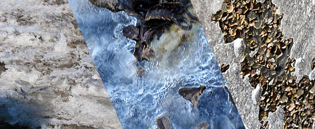
It’s always important to get good reference when building materials. Even if you are doing something cartoony great shots are about more than colour. Good reference tells you how the material acts. Ask yourself questions like: how does it reflect light? Are there any colour commonalities between all photos? Are some parts of the material giving of no specular highlights? My ice material is going to act as floor or wall material as it won’t be translucent. All of the ice in our reference looks patchy and that’s what I want. White is visible all the time as there is white noise all over these photos. These also all seem to be lit me a fairly bright source. You could have just grabbed any photo of ice and started looking at it for reference, but that’s not a good idea. You should think about the scale and the surrounding environment. Is this ice going to be seen far away, or close up? Ice looks really different at varied distances. If you took the properties of the middle shot and tried to use them for a floor in a fps game it might look odd. This is a really zoomed in shot of ice. If you were standing on top of it looking down you wouldn’t see close to that amount of detail. Especially the fine edge lighting on the cracks. So scale is important because It helps us to suspend belief. If the scale is off and the player notices they will immediately become disengaged and that’s no fun :( So decide how you want your ice to look and jump into Photoshop. We’re now going to setup the our material.

Photoshop

Within Photoshop we will create the diffuse, reflection, and specularity textures. We will be saving all of our images in the  Targa (TGA) format. Each channel in a TGA file has 8 bit’s of information. When you go to save a TGA in Photoshop you will get an option to select 24bit or 32 bit. Each colour of RGB is saved as one 8 bit channel. When you save a 32 bit Targa you get to include an extra channel. We will be using this feature to include our specularity texture in our diffuse file. I mention this because I don’t want you to just start saving files as 32 bit thinking they are better quality as there is no difference. From this point forward we want to be working in a new Photoshop file with a seamless texture as the base.
Diffuse and Specular maps (http://www NULL.terrymatthes NULL.com/wp-content/uploads/2010/12/m_101_icy_diffuse_spec NULL.png)

Diffuse Texture

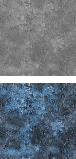
Let’s Duplicate (ctrl+j) our base diffuse layer and remove it’s saturation by accessing Hue/Saturation (ctrl+u) and pull the saturation all the way to the left. This will make the layer gray scale. To create some variation in the light we are going to choose the Magic Wand tool from the menu and start making multiple selections (shift+mouse1) across the layer. We want to pick chunks of the texture out so we can change their brightness and contrast. When you have a selection you like go ahead and access the Brightness/Contrast under the image >adjustments menu. Let’s change the brightness and contrast so these selections stand out more than the rest. To help you see the adjustments you’re making better try Hiding Selection Border under the view>show menu. When you’re happy with your results Unselect (ctrl+d) your selection and go back into the Brightness/Contrast function. We want to lower the overall brightness and contrast of our specular map. If things are too bright they will shine too much and your material will look like a white sheet. The final step is to Select Everything (ctrl+a) on our specular layer and Copy (ctrl+c) it. Now we want to look at our documents “channels”. These are under the “Windows” menu in Photoshop. If you click on this you will see 4 different “layers” in a window labeled “Red”, “Green”, and “Blue”. They represent the colour information for your entire texture. Click the “new layer” button at the bottom of the panel to create a new channel. By default it will be labeled “Alpha”. Select this channel and Paste (ctrl+v) your specular layer into it. Now your specular map will be saved in your alpha channel. Click back on the layers window and make sure make sure your diffuse layer is the visible layer.  Now we will save the file using “save as” and select TGA as our file type. When you hit “save” Photoshop will give you the option to save as a 32 bit file. We need to do this or we will loose that specularity map sitting in our Alpha channel.

Reflective Texture

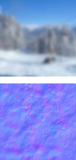
The reflective texture you use really depends on the environment you want to display your material in. For this example I don’t want a distinct reflection as much as I want a wash of colour to pass over the material. Find a picture you wish to use and paste it above your diffuse layer. Select your reflection layer and use Gaussian Blur (ctrl+alt+shift+g) to make any distinct forms unrecognizable. If you’re happy with your reflective texture go ahead and save it out as a 24 bit TGA. That’s 24 not 32. We don’t need that extra specular channel in this texture.

Crazy Bump

Normal and Reflection Maps (http://www NULL.terrymatthes NULL.com/wp-content/uploads/2010/12/m_101_icy_reflection_normal NULL.jpg)Normal Texture

If you haven’t installed CrazyBump get to to their website (http://www NULL.crazybump NULL.com) and download the free trial. When you’ve got the program up and running click the Folder button at the bottom left and choose the diffuse texture we saved out earlier. You will be presented with two choices after opening your file. The choices are just inverted height maps. Choose the one that best represents the contour of your diffuse material. When doing so remember that white is the high point and black is the low point. After choosing  you will be presented with a normal map and a set of sliders. These represent the different detail forms that will be present in your normal map texture. You want to move the sliders around until you get an accurate representation of your diffuse material form. When you’re finished click the save button and choose to save out only the normal map as a TGA. At this point it’s a good idea to copy this normal map into your Photoshop file containing the other maps. You always want to keep your assets for a single material in the same file. If you begin to run out of space, buy another HDD. Yes that’s right, you might have to spend some money. Who doesn’t like HDD shopping though? Honestly? If new computer parts don’t turn your “geek” on I’m curious as to why your reading a blog dedicated to video game technology tutorials. You’ve got “nerd” in you, it’s OK.

Unreal Development Kit

Setting Up Our Package

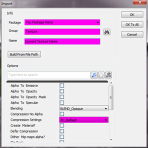
After launching the Unreal Development Kit Editor we want to open the content browser (ctrl+shift+f) and click the “Import” button at the bottom left of the content browser window. Now select all the files you want to import.  When you hit the “OK” button the UDK will start to import the textures one by one. For each texture you choose to import you have to set it’s import options in the dialogue box. The only thing I want you to keep an eye out for here is your normal map. When it comes time to choose it’s options change the “Compression Settings” from “TC_Default” to “TC_Normalmap”. Once complete you should be looking at a layout of all the textures you have imported. The last thing we want to do is go ahead and create a new material. To Do this right click in the empty space of your package and select “New Material”. An import dialogue box will appear again, but this time change the group name from “Texture” to “Material”. This will help keep your package organized. Now that you’re looking at your empty material we will start bringing our texture samples into it.

Unreal Development Kit Texture Import Options (http://www NULL.terrymatthes NULL.com/wp-content/uploads/2010/12/m_101_icy_importOptions NULL.jpg)Material Editor

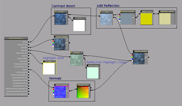
To add a texture into our material we’ll first make sure it’s highlighted in the content browser then hold down the “t” key and click with our mouse in the empty space of our material. You will need to do this for each node so lets go ahead and finish that. Below is a picture of our final node network for our ice material. If you’re new to the material editor it might look a little scary, but don’t worry I’m going to explain the network one node grouping at a time as we build this material. One quick note before we start: You can view the output of almost every node by clicking it’s black box in the upper left hand corner. It’s a nice feature for troubleshooting.
Icy Material Network Unreal Development Kit (http://www NULL.terrymatthes NULL.com/wp-content/uploads/2010/12/m_101_icy_MatNetwork NULL.jpg)

Diffuse Input

Part 1: Reflection The diffuse input is going to contain the reflection for our material and since it’s the most complicated part of our network I’d like to do it fist and get it out of the way. There will be two parts to this group, the reflection and  a contrast boost added after the reflection has been mixed with the diffuse texture. To set up the reflection we are going to need four nodes. So lets grab them all and place them on our canvas. the fist node is one already here, it’s our reflection texture sample. The second is an “Add” node. Hold down the “a” key and click on the canvas to drop one down. This node can also be found under the “Math” section on right right hand tree menu. The third node is a “Reflection Vector”. Drop one of these down by holding the “r” key and clicking on the canvas. This node can also be found under the “Vectors” section. Our last node is called a “Component Mask”. This node will help us hook up the Reflection Vector to the UV input of our Reflection texture sample.

If you become lost just refer back to the diagram of the node network posted above. Our Reflection Vector output will plug into the input on our Component Mask. Next the Component Mask output will plug into the “UVs” of our Reflection Texture Sample. Plug the top tab of our Reflection Texture Sample output into one of the Add node inputs. The top tab of any Texture sample represents all three colour values as opposed to just red, green, blue, or alpha as the ones beneath it do. Finally drag the top output of our Diffuse Texture Sample into to the 2nd Add node input. Now marquee drag a box around this group while holding down ctrl+alt. When you let go right click in empty space and choose the “New Comment” option in your menu. This lets you add a comment box around your selection.

Part 2: Contrast Boost The contrast boost is just a “Power” node. You can use Power nodes to increase or decrease the contrast of a network. This node has two inputs. The first is the Base and the second is the Exp or exponent. Drag a Power node onto the canvas from the “Math” section in the right hand menu. For a base input we will plug the output of our Add node created above. As for our Exponent we will use a Vector1Constant (“1″+mouse 1). A Exponent value of 1 will not change the texture. Going down from one will decrease the contrast and (you guessed it) going up will increase the contrast.

Emissive Input

For the Emissive channel we will Copy (ctrl+c) our Diffuse Texture sample and Paste (ctrl+v) it next to our diffuse input. Now drag the RGB tab (top) output into the Emissive input of our material. There wasn’t that easy :)

Specular Input

We want to add some colour to our specular and to do this me need to multiply it by a colour value. Luckily we have nodes that do just that. Hold down the “m” key and click to drop down a” Multiply” node. Next hold down the “3” key and click to drop down a “Constant 3Vector” node. The three values of the Constant 3Vector node can be used to represent RGB and when you put those together you get a colour.  Plug the output of the Constant3Vector node into one of the inputs of the multiply. In the other Multiply input connect the white tab of our diffuse texture. This is where our specular texture was stored when we saved it as a 32bit Targa in Photoshop. Lastly plug the output of the Multiply node into the Specular input of the material. Don’t forget you can view what the result of the Multiply node will look like by clicking the black box in it’s upper left hand corner.

Specular Power

The specular power controls the size of the highlight that is cast on your material. There is no hard and fast rule for this number as your lighting is affected by all the different components that make up your material. What worked for my material may not work for yours. Hold down the “1” key on the keyboard and click to get a Constant1Vector on your canvas and plug this into the Specular Power input of the material.

Normal Input

The last grouping of nodes we have to put together is our Normal Input. Lets start by connecting the RGB tab of our Normal Texture Sample to the Normal input of our material. Now we are going to “bump” those normals of the surface of our texture a bit to give the ice a translucent look. If you go to your menu on the right and scroll to the “Utility” section you will see a node called “Bump Offset”. Drag this node onto your canvas. Now drag the Alpha(Specular) output of your Diffuse Texture Sample into the “Height” input of our Bump Offset node. Connect the output of the Bump Offset to the Normal Texture Sample’s UV’s and then connect the RGB output of the Normal Texture Sample into the Normal input of the material. Increasing the Bump Offset values give the illusion of surface depth which lets you “look into” the ice. At any time you can hold down the “l key” and drag your mouse over your material preview to drag a light around and get a better feeling for how your material behaves when lit.

Conclusion

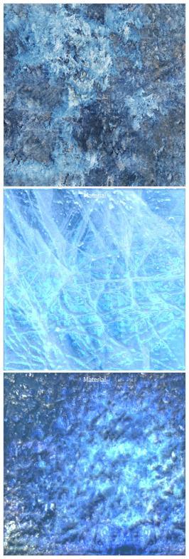
Final Ice Material With Alternate Versions (http://www NULL.terrymatthes NULL.com/wp-content/uploads/2010/12/m_101_seamless_finaltotal NULL.jpg)I hope you had as much fun creating your ice texture as I did writing this tutorial. If your not happy with your outcome try again. The material I’m showing as my final was the fifth one I had created. A lot of creating materials is just getting a handle on all of the different settings and knowing what to expect when you combine different networks inside the material editor. If you have any questions email me or post them below. As always I’d love to see your work so post a link or drop me a line. Before I go I just wanted to show a couple other ice textures I created along the way.

Further Reading

Seamless Textures In Photoshop (http://www NULL.terrymatthes NULL.com/articles/seamless-textures-in-photoshop/)

Program Shortcuts Used

Photoshop
New Layer (ctrl+shift+n)
Duplicate Layer (ctrl+j)
Hue/Saturation (ctrl+u)
Burn (ctrl+shift+b)
Dodge (ctrl+shift+d)
Unselect (ctrl+d)
Select Everything (ctrl+a)
Gaussian Blur (ctrl+alt+shift+g)

Unreal Development Kit
open the content browser (ctrl+shift+f)
Copy A Node (ctrl+c)
Paste A Node(ctrl+v)
Add Node (a+mouse1)
Multiply Node (m+mouse1)
Vector1Constant (1+mouse1)
Reflection Vector (r+mouse1)